K - 94, Waluj MIDC, Chh. Sambhajinagar (Aurangabad)-431136, Maharashtra, India.

We are Commited to Deliver Products built on the foundation of accuracy, durability, and innovation
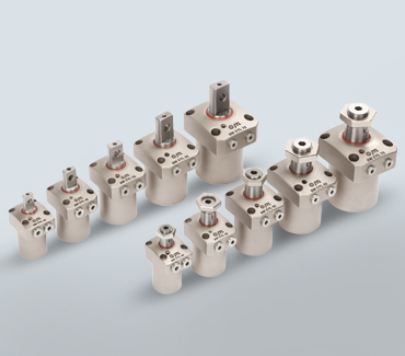
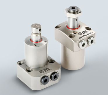
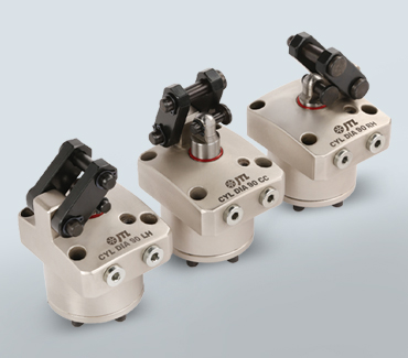
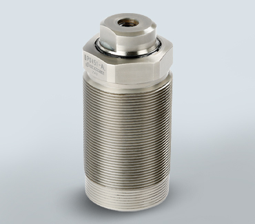
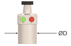
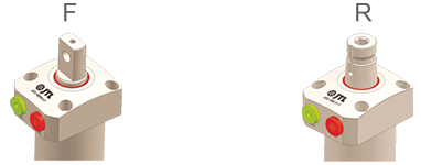
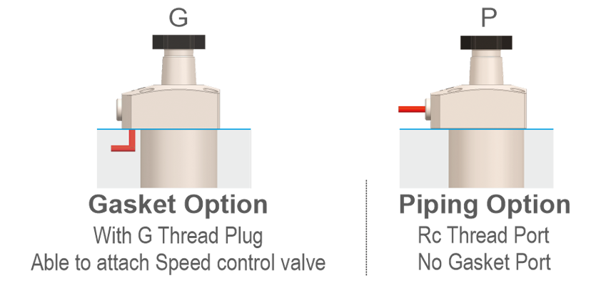
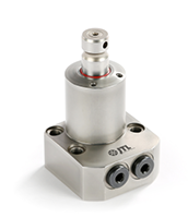
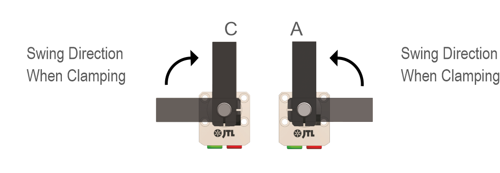
JSC Series Swing Cylinders are designed for precise swing motion and stable clamping under continuous industrial operation. Their robust construction, precision-machined internals, and optimized cam mechanisms ensure smooth swing action, accurate clamping, and reliable performance with minimal hydraulic pressure.
Swing cylinders are ideal for applications requiring clearance during loading/unloading, precise positioning, and secure hydraulic clamping in demanding machining and automation environments.
Model No. Indication

| Model No. | Unit | Ø40 | Ø48 | Ø55 | Ø65 | Ø75 |
|---|---|---|---|---|---|---|
| Cylinder Area For Locking | cm² | 5.00 | 6.95 | 10.3 | 13.4 | 20.3 |
| Clamping Force (F) (Calculation Formula) |
kN | P(1-0.0016XL) | P(1-0.0009XL) | P(1-0.0011XL) | P(1-0.0009XL) | P(1-0.0007XL) |
| 2.0920+0.0040XL | 1.489+0.0018XL | 1.0039+0.0011XL | 1.0039+0.0011XL | 0.5175+0.0006XL | ||
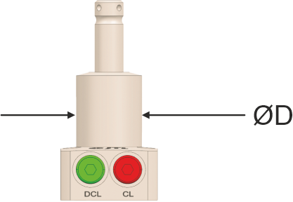
| Cylinder Inner Diameter | mm | 31 | 37 | 44 | 51 | 62 |
| Rod Diameter | mm | 18 | 22 | 25 | 30 | 35.5 |
| Full Stroke | mm | 14.5 | 15.5 | 18.5 | 20 | 24 |
| Swing Stroke | mm | 6.5 | 7.5 | 8.5 | 10 | 12 |
| Vertical Stroke | mm | 8 | 8 | 10 | 10 | 12 |
| Mix. Operating Pressure | MPa | 7 | ||||
| Min. Operating Pressure | MPa | 1.5 | ||||
| Withstanding Pressure | MPa | 10.5 | ||||
| Operating Temperature | °C | 0 ~ 70 | ||||
| Mass | kg | 0.8 | 1.2 | 1.8 | 2.6 | 3.9 |
| Usable Fluid | General Hydraulic Oil Equivalent to ISO-VG-32 | |||||
Model No. Indication
| Model | JSC B040 | JSC B060 | JSC B080 | JSC B100 | JSC B160 | JSC B200 | JSC B250 | JSC B400 |
|---|---|---|---|---|---|---|---|---|
| Cylinder Area for Locking (cm²) | 1.005 | 1.453 | 1.979 | 2.804 | 4.17 | 6.134 | 8.198 | 12.37 |
| Clamping Force (Calculation Formula) | F = P/10.94 + 0.036×L | F = P/7.57 + 0.024×L | F = P/5.53 + 0.0147×L | F = P/3.91 + 0.0094×L | F = P/2.59 + 0.0046×L | F = P/1.76 + 0.0028×L | F = P/1.32 + 0.0018×L | F = P/0.87 + 0.0011×L |
| Full Stroke (mm) | 14 | 15 | 18 | 19.5 | 24 | 26.5 | 32 | 35.5 |
| Swing Stroke (90°) (mm) | 6 | 7 | 8 | 9.5 | 11 | 13.5 | 16 | 19.5 |
| Vertical Stroke (mm) | 8 | 8 | 10 | 10 | 13 | 13 | 16 | 16 |
| Swing Angle Accuracy | 90° ±3° | |||||||
| Swing Completion Position Repeatability | ±0.5° | |||||||
| Max. Operating Pressure (MPa) | 35 | |||||||
| Min. Operating Pressure (MPa) | 7 | |||||||
| Withstanding Pressure (MPa) | 42 | |||||||
| Operating Temperature (°C) | 0 ~ 70 | |||||||
| Usable Fluid | General Hydraulic Oil Equivalent to ISO-VG-32 | |||||||